Plumbum Piping
What's the problem?
As a part of my APSC 169 class, myself along with my 3 other group members were presented a number of challenges for which we were to tackle one of. My group selected a challenge from the AquaHacking Binational engineering design competition which surrounds lead contamination:
Design technology solutions for the effective detection of lead service lines by pioneering remote sensing techniques for accurate lead infrastructure identification and developing safe, innovative methods for the disposal and replacement of lead pipes, ensuring the protection of public health and the environment.
Through research into the current situation surrounding lead contamination in Canada, we learned:
- Many older areas of Canada still have lead pipes due to the large expense involved in their replacement.
- Current methods for dealing with issues stemming from lead pipes all involve complete pipe replacement.
- Lead pipes contaminate both the water flowing through them as well as the soil and environment surrounding them. This raises the environmental impact as an additional avenue to tackle with our solution.
Design Goals
With these points in mind, we challenged ourselves to design a solution to this problem that:
- reliably reduces or eliminates lead in water so it is safe for consumption uses materials and technology
- that are already widely available can be procured in required quantities within a realistic timeframe
- to avoid prolonged exposure is easily transported and installed over a large area is low cost so
- it can be deployed affordably by residents or governments is environmentally sustainable — i.e.
- does not create new environmental issues while solving the lead problem
Project Organization
To ensure that we utilize our time as efficiently as possible throughout this project, it was essential that we stayed organized. To help manage this, I created a Gantt chart and used it to identify critical tasks that needed to be prioritized to ensure this project would be completed to the required schedule prescribe by our course.
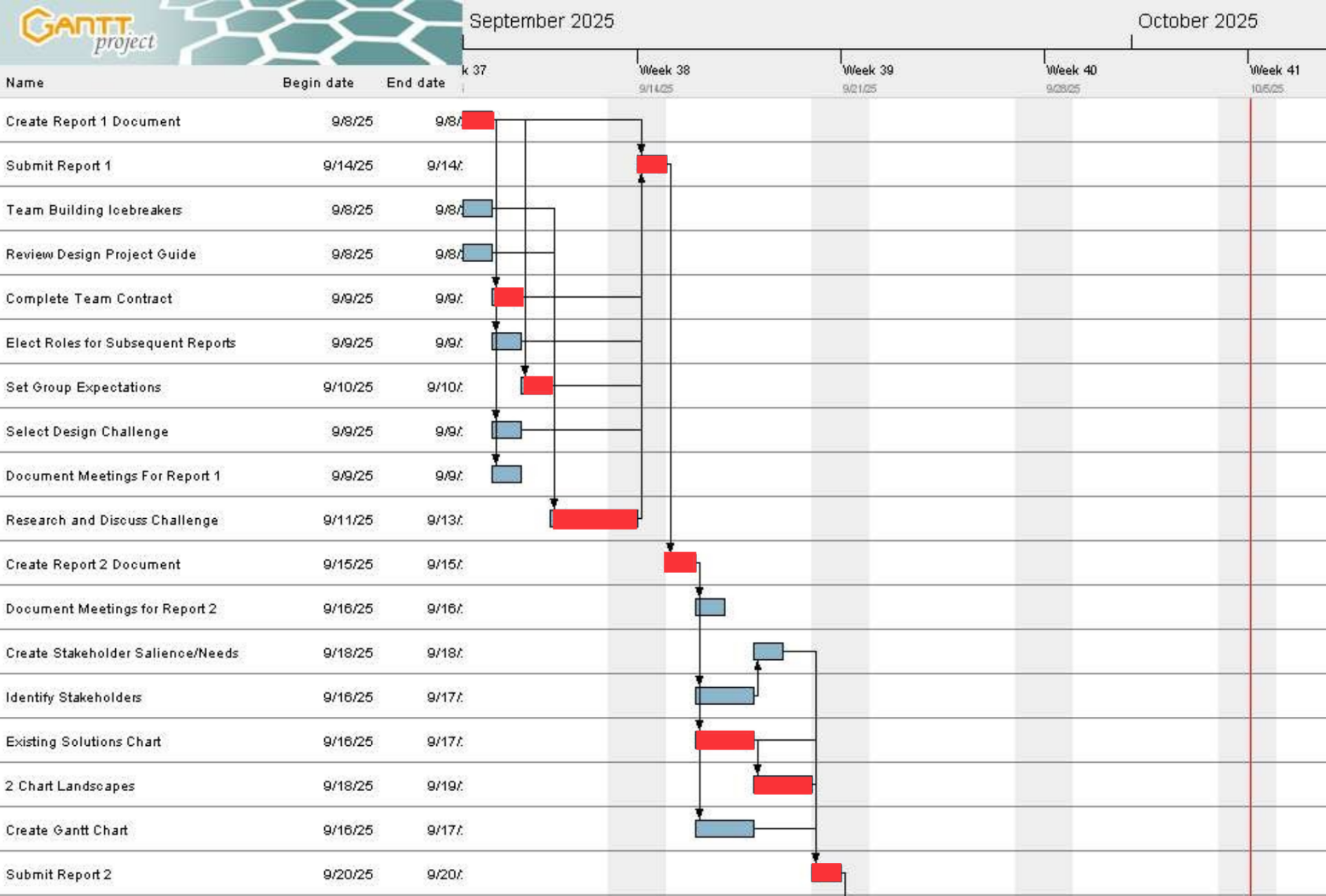
This was my first exposure to work breakdown structures and gantt charts. In order to create this gantt chart, I used GanttProject; however, I found it fairly unfriendly to use and later used Microsoft Project to create the second Gantt chart that was required later in the project.
Ideation
First, as a part of our ideation process, we initially followed the C-Sketch method to create various drawings of potential solutions. From those drawings, we discussed the merits of the various solutions and created a list of potential ideas to pursue. That list was then grouped into broader ideas which we then researched further to determine their feasibility. The list was then narrowed to 6 potentially promising concepts that would be taken forward to the next stage.
Concept Selection
To help us narrow down our ideas, we eliminated less feasible solutions using two methods, ranking and scoring. The solutions were ranked using a variety of voting methods to qualitatively determine the top 4 solutions. From there, the solution we would take forward to the rest of the project was determined quantitatively by using a weighted design matrix to score the solutions against our evaluation criteria.
This processed produced the initial version of what would eventually become Plumbum Piping. The concept was an inflatable pipe liner that could be installed into the inside of a pipe to prevent the contact of the drinking water with the lead pipes ensuring there is no contamination.
Iteration
Through research as a part of our material selection, we realized a critical flaw that required us to rethink a portion of the solution. In our original design, the intention was to utilize the water flowing through the pipe to inflate the liner. Based on standards for piping, we decided it would be best to use a fibreglass liner with a silicone based resin. Unfortunately this creates a major issue with our planned deployment method; while the resin cures, it must stay dry; contact with water would prevent it from curing.
To counteract this, we had two choices:
- Change the material of the liner such that it will not be affected by the water
- Change the deployment method to something that will not disrupt the curing of the resin
We decided to go with option 2. Instead of using the water to inflate the liner, large fans would be used to utilize air pressure to inflate the liner. This approach came with an unexpected benefit; not only did it not disrupt the curing process, it would speed up the curing process thereby shortening overall deployment time.
Prototyping
To validate our solution, I developed and tested 3 prototypes to asses a variety of risks. These prototypes were developed before the pivot to air based inflation; however, many still remain applicable and continue to address potential risks
Prototype 1
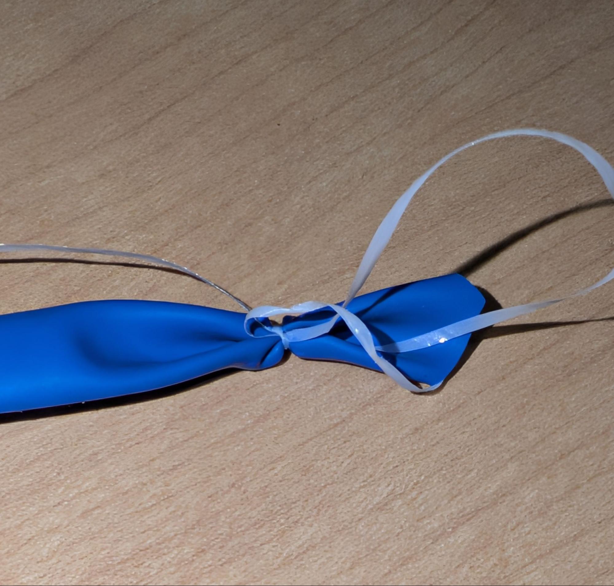
During the deployment of the liner, the end needs to be closed in order to maintain air pressure and not have air pass through the liner before it is fully deployed; however, once it is fully inflated, the end needs to be able to be opened ideally without the need to dig another access hole. To solve this, I designed a system that would allow the end to be opened by pulling on a rope.
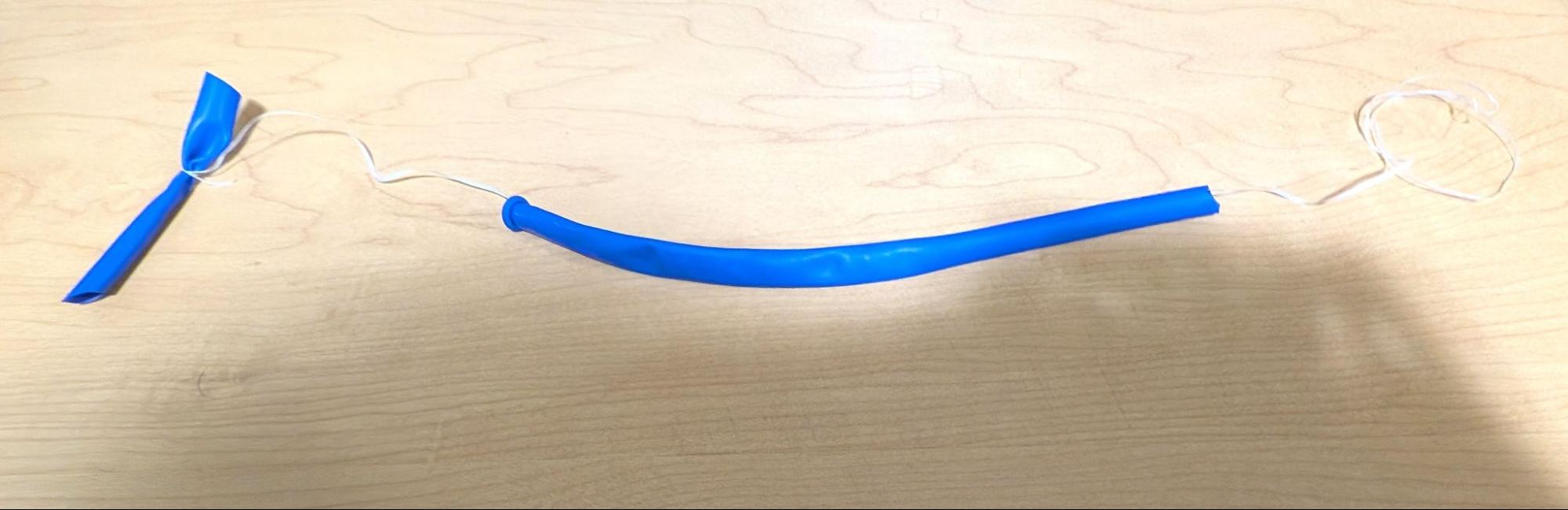
This prototype was constructed from 2 parts: a balloon animal type balloon and a piece of string. The balloon had its end removed in order to represent the liner. The string was inserted through the balloon and then tied in a slip knot such that pulling on the string would release the knot. By inflating the balloon then pulling on the string, I was able to successfully demonstrate the mechanism working as expected.
Prototype 2
The second prototype was originally going to be a physical prototype demonstrating the systems ability to deal with small punctures to the liner material during inflation. Unfortunately, I was unable to successfully inflate a balloon with a small puncture without the balloon tearing.
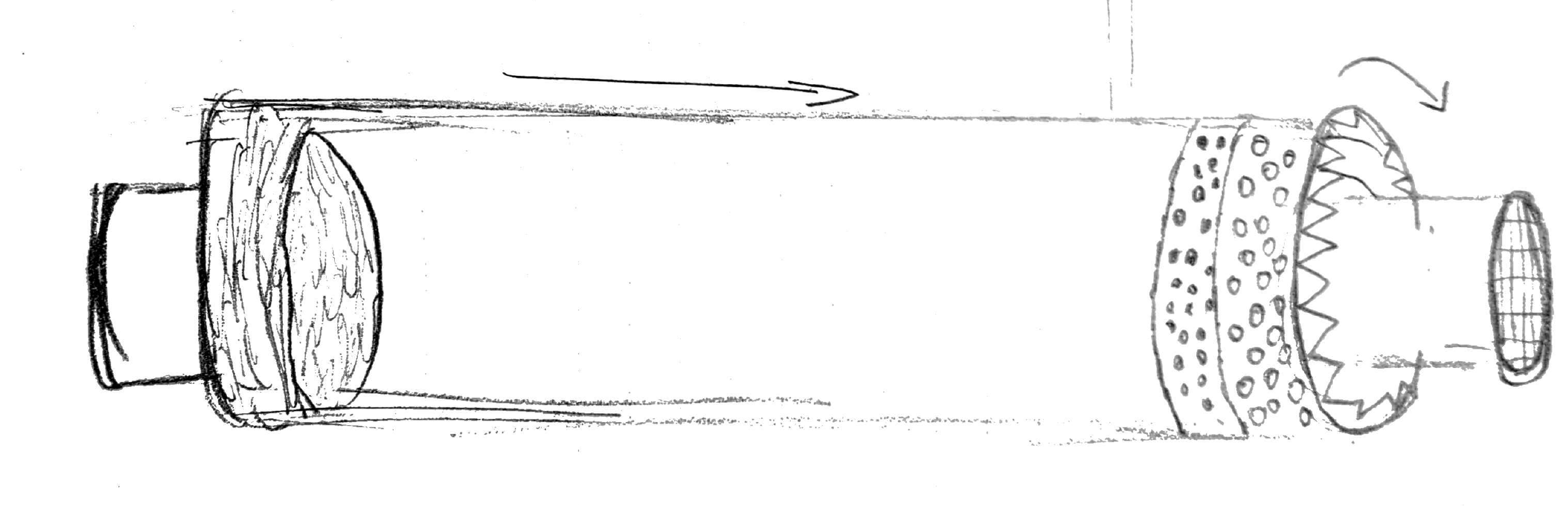
Because of this, this prototype was pivoted to a virtual prototype hypothesizing the liners ability to handle small leaks. This prototype unfortunately only applies to a system using a liquid for inflation rather than a gas. Despite its inapplicability to the final product, it was an important stepping stone in the process and for that reason I have included the diagram below.
Prototype 3
As the pipes that the liners are being installed in are often quite old and may be in varying condition, it was important to us that it would be able to handle being inserted into pipes in a variety of conditions. For this, I constructed an example of a pipe our of paper. I made a hole in the paper pipe and continued to increase the size of the hole until the pipe was no longer able to inflate properly.
This prototype provided us insight into potential stresses on the liner due to a damaged pipe allowing us to further confirm our material choices.
What's next?
Overall the project was a success. We were able to conceptualize a solution to a problem that is affecting thousands of Canadians. Unfortunately due to time, budget, and current skill constraints, we were unable to take this project further. This project allowed us to become familiar with the engineering design process and learn how it can help teams to design better products more efficiently.